Most of the components of a dam-free micro-hydropower system are identical to dam-associated systems and include the intake and screen, penstock, turbine, generator and interconnection. The major difference between a dam-associated and a dam-free system is the intake structure; so let’s look at that first.
Intake
The majority of hydroelectric projects use horizontal intakes. Compared to vertical intakes, they offer the advantage of more straightforward gates and trash racks. Intake structures can further be categorized by their configuration at the top water level – fully submerged or exposed intake structures. For waterfall applications – as in the dam-free micro-hydropower setting – a third type, collecting intake structures, can be the preferred option.
Submerged Intake Structures, as the name suggests, are fully submerged in an upstream lake or impoundment. They need a certain water depth (depending on intake size) to ensure the penstock will not pull in air, which could negatively affect system operation and efficiency. Submerged intakes are less prone to freezing of the lake as water flow remains constant underneath potential ice layers on top of the lake. They also are less prone to clogging, as much of the debris floats closer to the water surface than deep below. Submerged intake structures allow efficient flow regulation into the micro-hydropower system as well as down the waterfall. They are usually located at a deep location within the lake, making installation and repairs complex.
Exposed Intake Structures are located closer to the edge of the lake (or impoundment) or at least upstream of the waterfall within the stream bed. Size, shape, and location depend on the site-specific requirements but are mostly concrete boxes with openings towards the center of the lake. Trash racks and screens prevent floating debris and fish from entering the penstock sized for the site-specific requirements. Freezing can cause intake blockage. Maintenance staff will perform regular cleaning and clearing of the trash rack to ensure efficient water flow.

Exposed intake structures can be installed in combination with a partial dam removal or dam breach. The remainder of the old dam structure can help direct a larger amount of flow towards the intake structure while creating a free-flowing stream environment that is not preventing fish migration. Nuisance and high-priority dams can be removed without giving up the potential to generate renewable energy.
Collecting Intake Structures can be installed at an upper location on the waterfall, or above the waterfall in the stream. Designed correctly, they are mostly self-cleaning and low maintenance.
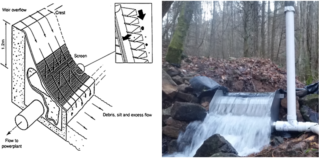
“Coanda”-screens and other fine screening racks allow fish[1] and debris to naturally flow downwards and follow the stream, while a fraction of the stream water falls into a collection channel/chamber installed (partially) across the stream/waterfall. The collection channel connects to a penstock on either side of the waterfall and transports the water down to the turbine. Turbine design and or channel design depend on each other and the best suitable location for the collection channel/chamber. An oversized penstock or a stilling chamber will create the necessary head for the micro-hydropower system.

Source: http://www.beraymuhendislik.com.tr/en/assets/img/sliders/revolution/coanda/coanda_intake_screens_1.png (left image) and
https://elginseparationsolutions.com/coanda-screens/ (right image).
One specific example of such an intake structure is called “Tyrolean weir,” in which water is taken from the main flow through a screen over a concrete gutter built into the streambed. The screen on the crest slopes downstream by 15-30 degrees increasing flow velocities and allowing sediment to be carried over it instead of blocking it. From the gutter, water enters a penstock which often drains into a sedimentation tank and then flows by gravity into the rest of the system.
At sites being considered for dam removal, a dam-free hydro system design could be proposed alongside a partial dam removal, leaving existing intake structures or low-level outlets. The partial removal still provides all the benefits a full removal would, plus it allows for easy installation of a dam-free micro hydropower system – in most cases only requiring upgrades for the intake screen.
Penstock
The penstock connects the intake structure with the turbine system. For micro-hydropower installations, the preferred material is HDPE (high-density polyethylene), a plastic that is durable, cost-effective, and light-weight. Even pipes of up to 18 inches (interior diameter) can be cut and installed manually without heavy construction equipment. This ease-of-use is important in uneven terrain near the waterfall as it limits costs and minimizes the environmental impact of system installation.
Besides its conveyance function, the penstock can also act as a water reservoir for smaller turbines, which helps minimize losses within the system as losses are proportional to the water velocity within the pipe: a larger pipe reduces the water velocity and thus friction losses. Instead of running a small diameter pipe all the way, the diameter should be reduced close to the turbine. The higher the elevation change, the higher the necessary pressure rating of the penstock. Piping manufacturers offer different wall thicknesses and coupler mechanism to address increasing pressure requirements. Standard lengths of pipe sections are 20, 40, or 50 feet but can vary by manufacturer.
Turbine
There are several types of hydroelectric turbines; they are all powered by the kinetic energy of flowing water as it moves, falls, and flows downstream. Turbines, in conjunction with generators, convert this energy into electricity. The turbine’s job is to catch the water and translate its movement into the rotation of a shaft to spin the rotor of a generator.
The local site parameters (head, flow, space) and the goals of the site owner dictate the turbine technology. The microhydrony.org-website offers additional guidance with a decision-making framework of how to choose the right turbine technology for your site.
Generator
Many turbine manufacturers work with specific generator types. The most common micro-hydropower applications are permanent magnet generators, where magnets rotate around conducting wires inducing an electrical current. Permanent magnet generators come in any size and design rotation speed. Manufacturers in China and India are flooding the generator market with low-cost generators for smaller applications. The design parameters depend on the turbine rpm (rotations per minute) and the expected torque – values that can easily be provided by the turbine manufacturer.
Interconnection
Interconnection refers to the connection of the micro-hydropower system to the public utility grid. The interconnection allows excess energy from the hydropower system to flow to the local power grid. In turn, the interconnection enables the grid to provide electricity to the site owner if local energy consumption exceeds generation output.
Not every system needs to be interconnected to the grid. Staying off-grid is a viable model if the hydro facility can approximately meet the dam owner’s onsite electricity consumption needs. The owner should be aware that they might need to adjust their consumption to match the daily generation as well as seasonally. Ideally the micro-hydropower system would be a little bit oversized compared to the onsite energy consumption. This will guarantee enough electricity even during low flow periods of the year.
But if the potential energy generation from the hydropower system in conjunction with other local renewable energy sources is either under or over the local energy consumption, it makes sense to interconnect with the utility grid. Smaller systems can be added to an existing grid-connected meter. Larger systems (above 30 kW capacity) might need upgrades to the existing utility line or meter. More information about the possible ways of selling hydroelectricity in New York State is found under Financial Models.
Miscellaneous
A micro-hydropower system might need different types of valves or gates to regulate the water flow, electrical monitoring devices to ensure safe operation, and other equipment to protect the system.
Additional signage might be needed to inform trail visitors about the system.
Now that we’ve covered the basics of dam-free micro-hydropower, let’s look at the assessment of the Lower Saw Kill setting beginning with site selection (as mentioned, there are three waterfalls that could be potential dam-free micro-hydropower projects). Or go a step back and read about the Design Requirements for Dam-Free Micro-Hydro.
[1] Bestgen, Bundy and Zelasko of the Larval Fish Laboratory, Department of Fishery and Wildlife Biology, Colorado State University reported in “Exclusion and Survival Rates of Early Life Stages of Fathead Minnows Released over Inclined Wedge-Wire Screens” (2001) on the exclusion and survival rates of fathead minnows passing over a Coanda (wedge-wire) screen. After releasing and recapturing fish downstream of varying lengths an exclusion rate of “ninety-six to one hundred percent” was obtained for fish greater than 12.5mm. Source: https://www.therrc.co.uk/MOT/References/EA_Screening_Intake_Outfalls.pdf

One response
[…] and key aspects of the necessary components of a dam-free micro-hydropower system. So read on: Part 2, Design Components […]