The first step in system design for a dam-free micro-hydro project at the Second Falls (Site 2) of the Saw Kill is identifying the best location for intake, conveyance system, and outlet of the hydropower system (see previous posts to review relevant technical requirements).
The vertical and horizontal distances, as well as the type of conveyance system, define the usable elevation change and operating head of the facility. The head, in combination with the hydraulic flow, will be the key parameter informing turbine size, electrical equipment configuration, and interconnection requirements.
Design and Installation
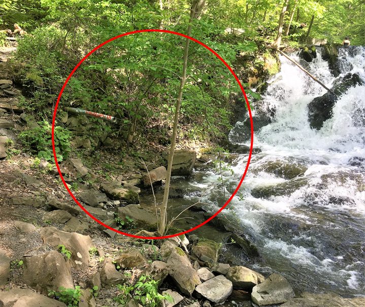
Site 2 offers two practical locations for the intake structure (both on the north side of the stream as access from the south is not possible):

Location A would allow for a significant portion of the stream to be diverted into the hydropower system and offers an additional 2 feet of head, but would also mean a longer penstock and increased system costs. Location B is where the historic intake for the swimming pool operation was located; remnants are still found in the stream.
While location B has the advantage of being closer to the main part of the waterfalls, the intake structure would need to be more complex and would lose up to 5 feet of elevation change compared with location A. Location A is thus the preferred layout and location for the intake structure. The gross head at the outlet is 24.3 based on drone footage.

The second integral part of the design is the outlet location, which also defines the main parameters of the penstock design. A penstock’s job is to convey the water from the intake to the turbine – hence, once both locations are defined the penstock path can be defined.
Proposed design suggests a turbine location close to the stream bank to utilize the maximum elevation change while allowing for maximum cost-efficiency, at a location at the foot of the waterfalls.

To connect the intake and the turbine location, the penstock will run close to the bank and the trail, and will need to be appropriately fixated to withstand high flow periods. The approximate path for the penstock with a total length of 110 feet, covering the elevation change of 24.3 feet looks like this:

Proposed penstock has an inside diameter of 16 inches and is made from HDPE (high-density polyethylene), a plastic that is durable, cost-effective, and light-weight for easy, manual installation. The diameter was chosen to balance ease of installation, material cost, visual impacts and friction losses. A larger diameter would further reduce friction losses and increase power output, but it would also drastically increase visual impacts of the penstock.
A valve located at the bottom end of the penstock could regulate the flow for the turbine system. Proposed Turbine is a 40 kilowatts (kW) Crossflow turbine that starts operation at 4 cubic feet per second (cfs) using a maximum flow of 25 cfs.

Source: https://www.turbinesinfo.com/cross-flow-turbine-how-does-it-work/
Cross Flow Turbine technology offers various benefits and is therefore the optimal choice for low-head dam-free micro-hydropower projects. The housing structure for the turbine can be fairly simple, almost vault-like. Based on the scenic setting, located next to a waterfall, a more complex powerhouse could be an attractive alternative.
To connect the system to loads, the closest point of interconnection is the building above the waterfall. An underground cable connection from the system at the foot of the waterfall will need to be run to that building. If parts of the penstock are to be placed under the trail (instead of just along the stream bank), the trench could be dug in conjunction. An alternative, visually less attractive options, is to run overhead lines up to the building.
Operations and Maintenance Costs
The system as designed is a low-maintenance system. The trash rack is self-cleaning and thus needs very little attention. The generation data can be monitored remotely and includes alert systems and automation if operation moves into unusual parameter realms. The system will likely not generate any energy during all of the summer months due to low flow conditions, allowing for necessary maintenance and repairs without losing income due to downtime.
The maintenance labor cost will be limited to regular inspections during the operational months and more extensive maintenance work during the summer period as needed. Insurance and taxes are assumed to be zero as this small facility likely would not impact Bard College’s existing insurance (negligible in size and associated risks compared to the rest of the campus) and the college does not pay property taxes.
Energy Estimates and Economics
Energy estimates are based on the flow assumptions presented in previous posts, and the head and system parameters outlined in the system design above. At a maximum flow of 25 cfs, the turbine will be able to generate close to 40 KW and will start operation at 7.5 cfs of usable flow. Based on those parameters, in conjunction with the estimate flow pattern of the Saw Kill, proposed dam-free micro-hydropower system is expected to generate up to 197,970 kWh annually – assuming enough flow (60% assumed) can actually be diverted through the intake structure spanning parts of the stream at Location A.
As this system would likely be interconnected with the grid and export excess energy (after net-metering) or via remote-net metering, the system’s monetary benefit depends on the Value of Distributed Energy Resources (VDER). The microhydrony.org-website explains the concept of VDER. Additionally, NYSERDA’s website presents more policy information as well as current pricing rates. The latest version of the value stack calculator (a tool to estimate the VDER for planned developments) assumes the VDER for this project to be around 8.3 Cents/kWh[3]. With 197,970 kWh / year at 8.3 Cents/kWh, the annual revenue would be $16,432.
Depending on the installation costs – here estimated at a total of $125,000 – the payback period would be around 8.6 years (permitting excluded, which could be substantial in terms of time spent) with a Return on Investment of 11.6%. We additionally conducted a sensitivity analysis regarding the flow data and investment cost and came to the conclusion that if both parameters worsened by 34% (34% less usable flow and 34% higher installation costs) the payback period would reach 15 years, which is still an acceptable payback period for a long lasting low-maintenance renewable energy source.
The full feasibility assessment report can be found here on microhydrony.org. We will share a summary of the Dam-Free Micro-Hydro assessment in our next post.
[3] It should be noted that current market energy prices (Locational Based Marginal Pricing, LBMP) are significantly lower than their average over the past 3 years – which is the baseline for the energy value within the VDER estimate. Using a VDER

No responses yet