Matt Deady, Professor of Physics, Director of the Physics Program, Bard College
All hydroelectric systems can be described by one simple process. The energy of the water turns a turbine wheel while this wheel is connected to a shaft. This shaft then rotates a generator within a group of magnets which creates a current within the generator, producing electric power. You can think of a hydroelectric turbine as the opposite process of a regular fan. Instead of electricity powering the fan then the fan generating wind, the water flow is driving the fan then the fan generates electricity.
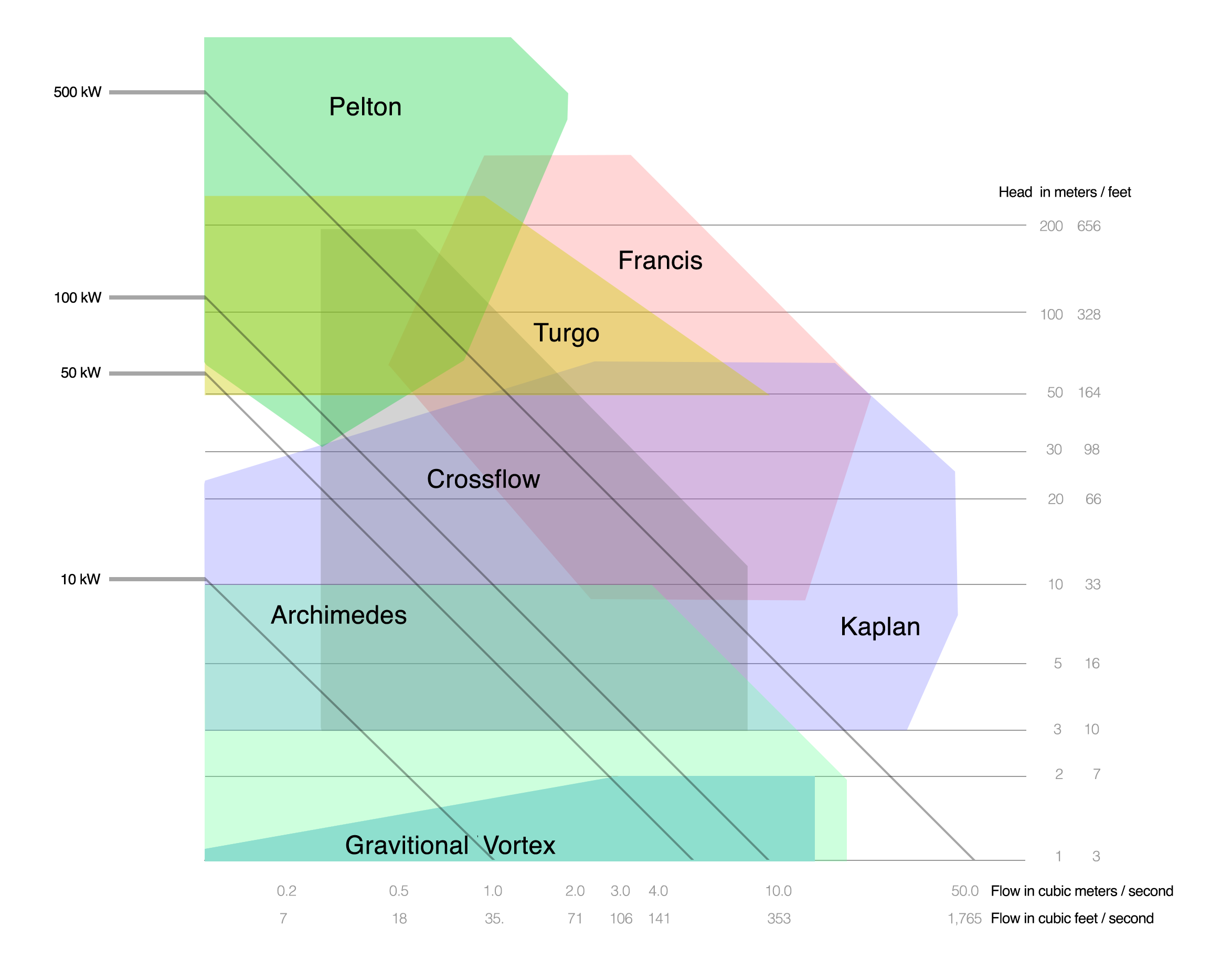
Many factors contribute to the type of turbine that is suitable for a site. The first two factors are available head and flow rate. The available head is the height from the turbine to the intake of the penstock. The flow rate is the volume of fluid which passes a point per unit time. Together, available head and flow rate help estimate how much energy can be produced from a site, as we detail in Calculate Maximum Power. For each head-flow combination, there are a selection of turbines that will work optimally within those conditions. The chart in Figure 1 helps determine which turbine is most suitable for your site.
Figure: Turbine Operating Ranges
Click here to expand the diagram.
Figure 1: Different turbines operate best in different conditions, courtesy of Current Hydro. By connecting the flow rate (x-axis) of your moving water and the head (y-axis) that your site has, this chart can also be used to estimate the power output from your site. The colored regions indicate the types of turbines which would work best for your head and flow conditions. For instance, For instance, h = 3 m and Q = 1.2 m³/s falls in the regions of the Archimedes Screw, Crossflow, and Kaplan turbines suggesting these might be good choices. These conventional turbines, which will be discussed in the next three sections, are generally divided into three categories: impulse, reaction and gravitational turbines.
Impulse Turbines
An impulse turbine operates with its runner (turbine wheel) in air, driven by jets of water. These jets increase the velocity of the flowing water by restricting the area which the water moves through. Think of the runner as a fan blade and the water jet as a hose. As you spray the water at the fan blade, the fan will begin to spin. If you partially covered the opening of the hose then the water would exit the hose at a higher velocity, causing the fan to rotate faster. There are many benefits to installing an impulse turbine. These types of systems include the Pelton, Turgo, Multi-Jet Pelton and the Cross-Flow turbines. One benefit is they are usually less expensive than other turbines because they do not require as much precision to manufacture or require pressure seals around the shaft. The main drawback to impulse turbines is they are generally unsuitable for low-head sites. The source of energy for the turbine is the kinetic energy created by the water jet, which requires a larger head value.

Figure 2: Impulse Turbine System – Kaplan Turbine (Wikimedia Commons)
Reaction Turbines
Reaction turbines are highly efficient and are ideal for medium to low head sites. These types of turbines include the Francis and Kaplan turbines. The efficiency of these systems is caused by the more complex manufacturing process that involves larger and more detailed blades as well as carefully profiled casings. Although this precision does increase cost, the extra expenses are offset by high efficiency. The runner in this case is fully immersed within the flowing water. As the water enters the turbine through the intake, the guide blades direct the water so that it approaches the rotor blades with a tangential velocity. These rotor blades are precisely angled in order to efficiently receive the incoming water, transfer its kinetic energy into rotational energy of the blades, and release the water radially. Here, as the water initially hits the rotor blade, a region of high pressure is created pushing the blade. Once the water loses its tangential velocity, a region of low pressure is created against the back of the following blade. This creates a pressure difference between one side of the blade and the other, which makes the runner spin as the blades.
Gravitational Turbines
A gravitational turbine is a system that uses gravity and water channeling to rotate a runner. This is slightly different than impulse and reaction turbines because it does not require special water jets or precision rotor blades to be manufactured in order to be efficient. This makes gravitational turbines relatively cost effective. These systems are ideal for low head sites and only require a low rotation speed which reduces the danger for fish passing through the turbine.
The Gravitational Vortex is a specific type of gravitation turbine. Water is directed through a channel tangentially into a cylindrical structure with an outlet at the bottom center. As the water enters the structure it begins to create a vortex which spirals toward the outlet. Once the water travels deeper into the structure it will come in contact with the blades of a horizontal turbine wheel suspended into the structure. This wheel is consistently rotated since the water is doing work on all of its blades simultaneously.
Similar to the Gravitational Vortex, the Archimedes Screw also uses gravity to generate rotational motion. Archimedes Screws were originally developed to transport water up and out of a body of water. All you had to do was rotate the shaft at the top of the system and water would be scooped up by the screw and carried to the top of the system. In such a case, energy is put into the system in order to move the water to the top of the screw. The opposite is the case for an Archimedes Screw hydro turbine. Water enters the top of the system and as gravity forces the water downward, the screw rotates, therefore turning the turbine.

Figure 5: Archimedes Screw (Wikimedia Commons)
To help dam owners and owners of potential dam-free micro hydropower sites assess their micro hydropower potential and design their general system layout, we’ve developed a Micro Hydropower Decision Making Framework, in the form of a flowchart, which is based on lessons learned throughout the demonstration micro hydropower project at Bard College. The Decision-making Framework aims to assist interested parties in navigating their micro hydropower options and focuses on a project’s technological feasibility, considering the starting point (i.e. existing dam, no dam, other infrastructure), key decision points and potential fatal flaws (i.e. head, flow, proximity to utility infrastructure, system size), and will ultimately suggest a micro hydropower design. The visual flowchart will assist navigation for stakeholders who have taken the option to install micro hydropower focusing on technical feasibility and potential “fatal flaws”. A detailed description of various self-assessment steps and options, as well as recommendations and necessary considerations are provided in the tool’s guidebook.

2 Responses
[…] The dam functioning as a barrier for aquatic species is an existing issue. Certain hydropower design options show promise in enhancing fish passage at some level. Because the effectiveness of such designs on […]
[…] Different types of micro-hydro turbines are better suited for various flow and head conditions. In rough terms, impulse turbines need a high head to give the water jets high velocity, and low head situations are better suited to reaction turbines. A more detailed discussion of choosing a turbine is given in the Types of Turbines post. […]